Fittings · ASME
Butt-weld fittings to ASME B16.9: dimensions and tolerances
Elbows, tees, reducers, caps and stub ends to the American standard: choose the shape – each has its own page with dimension table and dimensioned drawing. This page gives the stub ends, the limit deviations of all shapes and the welding ends. The wall is set by the schedule of the pipe.
- Standard
- ASME B16.9
- Sizes
- type × NPS
- Materials
- e.g. ASTM A234 WPB, A403 WP316L, A420 WPL6
- Availability
- from stock or to order
Choose the shape
Each shape has its own page with the dimension table, the dimensioned drawing and the limit deviations.
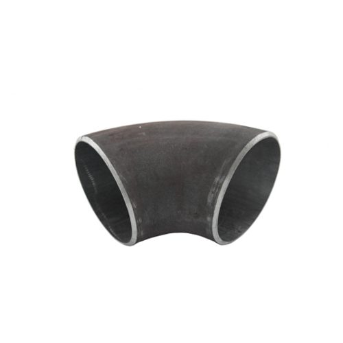 Elbows 90°, 45° and 180°
 Tees equal and reducing
 Reducers
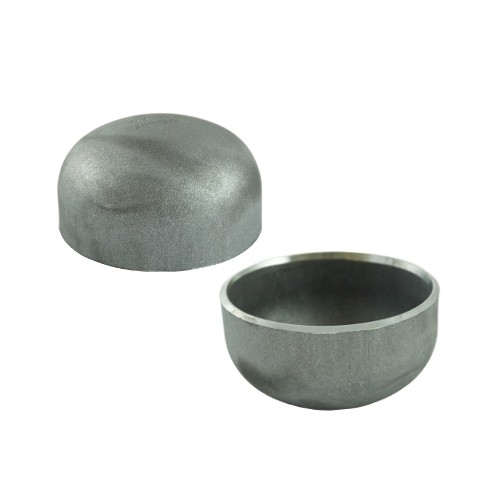 Caps
Choose a size
Lap joint stub ends: choose NPS – the result shows F, G and R in mm with inches in brackets. In the third field, choose the wall thickness of the connecting pipe – the result shows the wall thickness at the welding end and the minimum wall thickness.
Dimension table ASME B16.9 – lap joint stub ends
Stub end (lap joint)
Show full table · more than 10 rows
| NPS | D mm (in) | F mm (in) | G mm (in) | R mm (in) | Kind of value | Availability |
|---|---|---|---|---|---|---|
| 1/2" | 23 (0.896) | 76 (3) | 35 (1.38) | 3 (0.12) | market dimension | available on request |
| 3/4" | 28 (1.106) | 76 (3) | 43 (1.69) | 3 (0.12) | market dimension | available on request |
| 1" | 35 (1.376) | 102 (4) | 51 (2) | 3 (0.12) | market dimension | available on request |
| 1 1/4" | 44 (1.716) | 102 (4) | 64 (2.5) | 5 (0.19) | market dimension | available on request |
| 1 1/2" | 50 (1.965) | 102 (4) | 73 (2.88) | 6 (0.25) | market dimension | available on request |
| 2" | 62 (2.456) | 152 (6) | 92 (3.62) | 8 (0.31) | market dimension | available on request |
| 2 1/2" | 75 (2.966) | 152 (6) | 105 (4.12) | 8 (0.31) | market dimension | available on request |
| 3" | 91 (3.596) | 152 (6) | 127 (5) | 10 (0.38) | market dimension | available on request |
| 3 1/2" | 104 (4.096) | 152 (6) | 140 (5.5) | 10 (0.38) | market dimension | available on request |
| 4" | 117 (4.593) | 152 (6) | 157 (6.19) | 11 (0.44) | market dimension | available on request |
| 5" | 144 (5.683) | 203 (8) | 186 (7.31) | 11 (0.44) | market dimension | available on request |
| 6" | 171 (6.743) | 203 (8) | 216 (8.5) | 13 (0.5) | market dimension | available on request |
| 8" | 222 (8.743) | 203 (8) | 270 (10.62) | 13 (0.5) | market dimension | available on request |
| 10" | 277 (10.913) | 254 (10) | 324 (12.75) | 13 (0.5) | market dimension | available on request |
| 12" | 328 (12.913) | 254 (10) | 381 (15) | 13 (0.5) | market dimension | available on request |
| 14" | 360 (14.17) | 305 (12) | 413 (16.25) | 13 (0.5) | market dimension | available on request |
| 16" | 411 (16.18) | 305 (12) | 470 (18.5) | 13 (0.5) | market dimension | available on request |
| 18" | 462 (18.19) | 305 (12) | 533 (21) | 13 (0.5) | market dimension | available on request |
| 20" | 514 (20.24) | 305 (12) | 584 (23) | 13 (0.5) | market dimension | available on request |
| 24" | 616 (24.24) | 305 (12) | 692 (27.25) | 13 (0.5) | market dimension | available on request |
from stock · to order · available on request – what is available how fast, we clarify on request.
Dimensions: as the market supplies them – from manufacturers’ and suppliers’ documentation and from our own product data, checked against ASME B16.9. Tolerances: limit deviations from manufacturers’ and suppliers’ documentation. The dimensions are the same for every schedule – the wall at the welding end is the pipe wall.
The table shows the market dimensions. What we carry from stock or to order is marked – the other sizes we procure on request.
Limit deviations
For the fitting types in the tables above, by size range. The wall may be 12.5 % below the nominal wall at any point, with no upper limit.
Show full table · more than 30 rows
| Dimension | NPS | Limit deviation |
|---|---|---|
| Outside diameter at the welding end D, D2 | 1/2 to 2 1/2 | +1.5 / −0.8 |
| Outside diameter at the welding end D, D2 | 3 to 3 1/2 | ±1.5 |
| Outside diameter at the welding end D, D2 | 4 | ±1.5 |
| Outside diameter at the welding end D, D2 | 5 to 8 | +2.3 / −1.5 |
| Outside diameter at the welding end D, D2 | 10 to 18 | +4.1 / −3.0 |
| Outside diameter at the welding end D, D2 | 20 to 24 | +6.3 / −4.8 |
| Outside diameter at the welding end D, D2 | 26 to 30 | +6.3 / −4.8 |
| Outside diameter at the welding end D, D2 | 32 to 48 | +6.3 / −4.8 |
| Inside diameter at the welding end | 1/2 to 2 1/2 | ±0.8 |
| Inside diameter at the welding end | 3 to 3 1/2 | ±1.5 |
| Inside diameter at the welding end | 4 | ±1.5 |
| Inside diameter at the welding end | 5 to 8 | ±1.5 |
| Inside diameter at the welding end | 10 to 18 | ±3.0 |
| Inside diameter at the welding end | 20 to 24 | ±4.8 |
| Inside diameter at the welding end | 26 to 30 | ±4.8 |
| Inside diameter at the welding end | 32 to 48 | ±4.8 |
| Centre-to-end A, B (elbows) · C, M (tees) | 1/2 to 2 1/2 | ±1.5 |
| Centre-to-end A, B (elbows) · C, M (tees) | 3 to 3 1/2 | ±1.5 |
| Centre-to-end A, B (elbows) · C, M (tees) | 4 | ±1.5 |
| Centre-to-end A, B (elbows) · C, M (tees) | 5 to 8 | ±1.5 |
| Centre-to-end A, B (elbows) · C, M (tees) | 10 to 18 | ±2.3 |
| Centre-to-end A, B (elbows) · C, M (tees) | 20 to 24 | ±2.3 |
| Centre-to-end A, B (elbows) · C, M (tees) | 26 to 30 | ±3.0 |
| Centre-to-end A, B (elbows) · C, M (tees) | 32 to 48 | ±4.8 |
| Length H (reducers) | 1/2 to 2 1/2 | ±1.5 |
| Length H (reducers) | 3 to 3 1/2 | ±1.5 |
| Length H (reducers) | 4 | ±1.5 |
| Length H (reducers) | 5 to 8 | ±1.5 |
| Length H (reducers) | 10 to 18 | ±2.3 |
| Length H (reducers) | 20 to 24 | ±2.3 |
| Length H (reducers) | 26 to 30 | ±4.8 |
| Length H (reducers) | 32 to 48 | ±4.8 |
| Length E, E1 (caps) | 1/2 to 2 1/2 | ±3.0 |
| Length E, E1 (caps) | 3 to 3 1/2 | ±3.0 |
| Length E, E1 (caps) | 4 | ±3.0 |
| Length E, E1 (caps) | 5 to 8 | ±6.3 |
| Length E, E1 (caps) | 10 to 18 | ±6.3 |
| Length E, E1 (caps) | 20 to 24 | ±6.3 |
| Length E, E1 (caps) | 26 to 30 | ±9.7 |
| Length E, E1 (caps) | 32 to 48 | ±9.7 |
This information does not replace purchasing the standard. The limit deviations are given in full in ASME B16.9-2024, section 11 – the minimum wall thickness at the welding end in section 11.1. Available from: ASME (asme.org).
How to measure
- Outside diameter D: measure at the bevel, twice at right angles – the body of a formed fitting may be thicker and is not the reference
- Wall T: the fitting is ordered by schedule, the wall at the bevel equals the pipe wall – measure with an ultrasonic gauge or at the cut face, 87.5 % minimum applies
- Centre-to-end A (90° elbow): lay the elbow on a plate, measure from the bevel face to the intersection of the two leg axes – for a long radius elbow this equals 1.5 × NPS in inches, so a 4 in LR elbow measures 6 in (152 mm)
- Centre-to-end B (45° elbow): not half of A – B = A × tan 22.5°, the tables round it (4 in LR: 2.50 in / 64 mm)
- 180° return: O is centre-to-centre of the two legs (3 × NPS for LR), K is back-to-face – the installed length – check the alignment of the two ends against a straightedge (U)
- Tee: C from the run axis to the run bevel, M from the run axis to the outlet bevel – on reducing tees M is shorter than C, the run length C does not change with the outlet size
- Reducer H: end to end along the axis – the same for concentric and eccentric – on the eccentric reducer measure along the flat generatrix
- Cap E: from the bevel face to the crown – heavy-wall caps (Sch 160, XXS) are longer (E1), the only B16.9 dimension that changes with the wall
- Stub end: F overall length, G lap diameter (fits the bore of the lap joint flange, B16.5 type LJ), R fillet radius – check G and R together with the flange of the same class
Welding ends to ASME B16.25
How the ends of pipes and fittings are prepared for butt welding – unless the order says otherwise:
- wall thickness below x (x = 0.19 in / 4.8 mm for carbon and ferritic alloy steel, 0.12 in / 3 mm for austenitic steel): ends cut square or slightly chamfered, at the manufacturer’s option – no bevel
- wall thickness x to 0.88 in (22 mm) inclusive: plain bevel 37.5° ± 2.5°, root face 0.06 in ± 0.03 in (1.6 mm ± 0.8 mm)
- wall thickness over 0.88 in (22 mm): compound bevel – 37.5° ± 2.5° from the root face up to 0.75 in (19 mm), then 10° ± 2.5° to the outside, root face 0.06 in ± 0.03 in (1.6 mm ± 0.8 mm)
- transition contours from the bevel into the body of the fitting follow ASME B16.9 (maximum envelope) – the catalogue refers to the standard
- minimum wall thickness at the end 87.5 % of nominal (pipe rule) – inside diameter and nominal wall at the ends are specified by the purchaser
- the same bevel geometry applies to pipe (B36.10M ends), fittings (B16.9) and welding neck flanges (B16.5 hub end) – B16.25 is the common end-preparation standard
How to read the tables
The letters above the columns are the dimension letters of the standard: A centre-to-end of the 90° elbow, C and M centre-to-end of run and branch on the tee, H the length of the reducer, E the length of the cap. On the long-radius elbow A is 1.5 times the nominal size in inches – a 4-inch elbow measures 6 inches from centre to end.
Compared with European fittings to EN 10253: the same outside diameters, but different centre-to-end dimensions, and the schedule takes the place of types A and B – never mix the tables. The wall thickness per schedule is listed under steel pipe to ASME B36.10M, the profile of the standard under ASME B16.9.
Frequently asked questions
Where do I find the dimensions of butt weld fittings to ASME B16.9 in millimetres?
The dimension tables on this page give outside diameter and construction dimensions (center-to-end, length, radius) per fitting type and NPS to ASME B16.9 in millimetres with inches in brackets, plus the tolerances.
Measuring the part yourself? D and T at the welding end, the centre-to-end dimension A of the 90° elbow and how to calculate it from the outside – with a measuring picture to ASME B16.9. How to measure correctly
Your inquiry to Zickwolff
Send us what you have – designation, standard, quantity, date. We will clarify the rest with you.
One item or a question
Send inquiry
Not in stock? We procure it – single items too.
Designation, standard and quantity are enough.
Several items
Send bill of materials
200 items? One parts list is enough – we deliver complete.
Attach it as a file.
Helpful if already known: project and country, date needed, certificates, packaging and language of the packing lists. If anything is missing, we will ask.
It is urgent
Request express
When do you need it? Express delivery, to the site if required.
Tell us by when you need the material – we will tell you what is possible.