Dimension table · Flanges · Type 13
Threaded flange type 13: dimensions and dimensional drawing to EN 1092-1
EN 1092-1 (formerly DIN 2566)PN 6–40DN 10–150Dimensions in mmfrom stock or to order
Dimensional drawing for your size
EN 1092-1 covers the greyed-out sizes. Our dimension overview lists them as order dimensions – see the table “Further deliverable dimensions” below.
Threaded flange · Type 13 · DN 100 · PN 16
Threaded flange type 13 in 3D – rotatable, all sizes DN 40 to DN 125
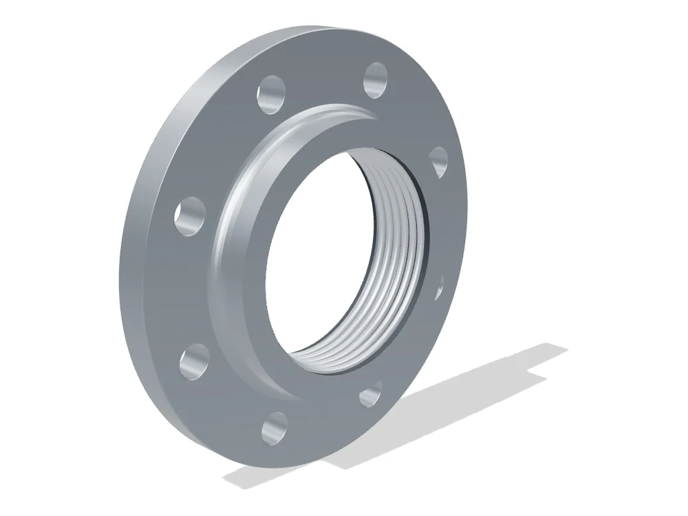
How to use the dimensional drawing – with example and direct link
Choose the pressure rating and nominal size – the drawing and dimension table then show exactly this version, with the values written directly in the drawing instead of just the dimension letters. The tables for the nominal sizes covered here are further down the page.
How it works: Choose PN 16 in the field “Pressure rating” and DN 100 in the field “Nominal size”. The dimensional drawing immediately shows every dimension of the threaded flange type 13 with tolerances, the table below all sizes. “Print this size as PDF” takes the drawing with you.
Example DN 100 PN 16: outside diameter D 220 mm, bolt circle diameter K 180 mm, bolt holes n × L 8 × ⌀18 mm, bolt size M16, flange thickness C2 20 mm, raised-face diameter d1 158 mm.
Direct link to this size: https://www.zickwolff.de/wissen/en/flanges/threaded-flange-type-13/?pn=16&dn=100
Technical basis: DIN EN 1092-1:2018-12. Zickwolff has prepared this presentation for practical use, with our own structure, our own designations and a statement of what kind of value each figure is. The original standard governs normative requirements.
| Property | Value | Type of information |
|---|---|---|
| basic data | ||
| nominal size | DN 100 | standard dimension |
| pressure rating | PN 16 | standard dimension |
| availability | from stock or to order | trade information |
| connecting dimensions The dimensions that decide the fit with the mating flange. | ||
| outside diameter D | 220 mm | standard dimension |
| bolt circle diameter K | 180 mm | standard dimension |
| bolt holes n × L | 8 × ⌀18 mm | standard dimension |
| bolt size | M16 | standard dimension |
| flange thickness C2 | 20 mm | standard dimension |
| sealing face | ||
| raised-face diameter d1 | 158 mm | standard dimension |
| raised-face height f1 | 3 mm – the plate thickness C2 includes it | standard dimension |
| thread and hub | ||
| internal thread | Rp 4 – parallel internal thread to EN 10226-1; minor diameter 110.1 mm, major diameter 113 mm, pitch 2.3 mm | standard dimension |
| height H1 | 40 mm | standard dimension |
| hub diameter N2 | 140 mm | standard dimension |
| corner radius R1 | R 8 mm | standard dimension |
Without an entry in the “Type of information” column: standard dimension. A dimension that EN 1092-1 specifies for this size.
Where exactly it is measured
- outside diameter D
- largest diameter of the flange plate, measured across the edge
- bolt circle diameter K
- diameter of the circle through the centres of the bolt holes – with an even number of holes, from hole centre to opposite hole centre
- bolt holes n × L
- count the holes, then measure the diameter of one hole – the hole is always larger than the bolt (example: hole 18 mm, bolt M16)
- raised-face diameter d1
- diameter of the raised face, measured across its outer edge
- flange thickness C2
- measure from the sealing face to the back of the flange plate, not at the hub. The projecting raised face is already included and is not added
- internal thread
- A designation, not a measured value: “Rp 2” does not mean a diameter of 2 inches. How to determine it without a gauge. (1) Measure the outside diameter of the thread, i.e. across the thread crests, into the hole from the sealing-face side. (2) Measure the pitch: count ten threads, measure the distance and divide by ten – measured over a single thread you can easily be out. (3) Look up both values in the table of EN 10226-1. The minor diameter is the smallest diameter and the one a caliper finds first in the hole – it belongs to the same row. Rp is PARALLEL: if the diameter differs at the front and at the back, you have a taper thread Rc in front of you and not this part
- height H1
- from the sealing face to the top edge of the hub
- hub diameter N2
- outside diameter of the cylindrical hub
- raised-face height f1
- height by which the raised face projects above the flange plate
Tolerances (limit deviations): what range the standard permits
For each dimension the range that EN 1092-1 permits is given – minimum and maximum instead of the deviation that would first have to be worked out. In the drawing this is shortened to tolerance – the word everyone uses in practice. In technical terms the two values given are the limit dimensions of the dimension, their distance is the tolerance and the deviations from the nominal size are the limit deviations. The basis is Table 22 and Table 23 – where the standard specifies nothing, that is stated.
These dimensions have two limit deviations – which one applies depends on the specific part
For the following dimensions the standard specifies two limit deviations. Which one applies does not depend on the nominal size but on the specific part. Both cases are therefore written out.
This answer determines: flange thickness C2.
flange thickness C2 – measure from the sealing face to the back of the flange plate, not at the hub. The projecting raised face is already included and is not added
Is the flange machined on both faces? (this refers to the two annular faces of the flange plate: the sealing face at the front and the nut bearing face at the back, on which the nuts sit. Machined on both faces means both are faced flat – with fine turning marks and an even sheen. A look at the back is enough: turned bright, or left as-forged with forging or rolling skin)
- machined on both faces flange thickness limit dimensions 18.5 to 21.5 mm (±1.5 mm)
- machined on the front face only, or not machined flange thickness limit dimensions 18.5 to 24 mm (+4 / −1.5 mm)
- I don't know both cases remain
Further properties with limit deviations
These properties have no nominal dimension in the dimension table, but the standard limits them. For incoming inspection they are often the decisive ones – they are what makes a bolted joint fail on site.
| distance between adjacent bolt holes | limit deviation ±1 mm |
|---|---|
| eccentricity of the machined sealing face | at most 2 mm |
| parallelism of nut bearing surface and sealing face | machined: at most 1° · not machined: at most 2° |
Measuring on the part: the dimensions in the picture
Every dimension has its reason – whoever knows why they measure, measures better.
Where the standard gives no limit deviation of its own
- corner radius R1 – EN 1092-1 specifies no separate limit deviation for this dimension. The general tolerance to ISO 2768-1 applies. The tolerance class is not specified in EN 1092-1 and is to be agreed between purchaser and manufacturer. For radii there is a separate table there, not the one for linear dimensions.
Sources of the limit deviations (14 entries)
- flange thickness (machined on both faces) – Table 22, flange thickness C1, C2, C3, C4, all types (machined on both faces), over 18 to 50 mm thickness
- flange thickness (machined on the front face only, or not machined) – Table 22, flange thickness C1, C2, C3, C4, all types (machined on the front face only), type 02 and 04 (unmachined), over 18 to 50 mm thickness
- distance between adjacent bolt holes – Table 22, centre to centre of adjacent bolt holes, all types, bolt size M10 to M24
- eccentricity of the machined sealing face – Table 22, eccentricity of machined sealing face diameter, all types, over DN 65 (footnote d)
- parallelism of nut bearing surface and sealing face (machined) – Table 22, parallelism between nut bearing face and flange sealing face, all types (machined bearing face), all DN
- parallelism of nut bearing surface and sealing face (not machined) – Table 22, parallelism between nut bearing face and flange sealing face, all types (unmachined bearing face), all DN
- outside diameter – Table 22, outside diameter D, all other types, up to DN 150
- bolt circle diameter – Table 22, bolt circle diameter K, all types, bolt size M10 to M24
- bolt holes – Table 22, hole diameter L, all types, bolt size M10 to M24
- height – Table 22, length dimensions of the hub H1 to H5, over DN 80 to DN 250
- hub diameter – Table 22, hub diameter N2, N3, types 12/13, over DN 50 to DN 150
- corner radius – Table 23, footnote a: dimensions for R1 for types 11, 12, 13, 21 and 34 see Table 10 to Table 21 – no limit deviation of its own, clause 5.9 applies
- raised-face diameter – Table 22, sealing face diameter d1, all types, up to DN 250
- raised-face height – Table 22, sealing face height f1, all types (sealing face type B, D, F and G), over DN 32 to DN 250, nominal value 3 mm
This information does not replace the standard itself. Only the limit deviations for the size selected here are reproduced. In full – for all nominal sizes, pressure ratings and flange types – they are given in DIN EN 1092-1:2018-12, Table 22 and Table 23. Where to obtain it: DIN Media.
Why limit deviations exist at all and how to read them is explained on a page of its own: Tolerances and limit deviations.
Dimensions are nominal dimensions to EN 1092-1 and do not replace the data sheet of the actual item. No statement about pressure or temperature suitability and no statement about the material. DN is a reference number, not a dimension in millimetres – the inside diameter differs from it. Direct link to this size
How to measure correctly
Four measurements identify a flange: outside diameter D, bolt circle K, the number and diameter of the bolt holes n × L, and the flange thickness C. Measure the bolt circle from the centre of one hole to the centre of the opposite hole – or, more easily, from the outer edge of one hole to the inner edge of the opposite one, which gives the same value. Measure the flange thickness from the sealing face to the back of the plate: a raised face is already included in C.
- outside diameter D
- largest diameter of the flange plate, measured across the edge
- bolt circle diameter K
- diameter of the circle through the centres of the bolt holes – with an even number of holes, from hole centre to opposite hole centre
- bolt holes n × L
- count the holes, then measure the diameter of one hole – the hole is always larger than the bolt (example: hole 18 mm, bolt M16)
- raised-face diameter d1
- diameter of the raised face, measured across its outer edge
- distance between adjacent bolt holes
- with equal holes, measure from the outer edge of one hole to the inner edge of the other hole (in the measuring direction that is the same side) – half a hole here cancels half a hole there: exactly the centre distance. Applies to the bolt circle K as to the hole spacing, as long as both holes are the same size
- flange thickness C2
- measure from the sealing face to the back of the flange plate, not at the hub. The projecting raised face is already included and is not added
- internal thread
- A designation, not a measured value: “Rp 2” does not mean a diameter of 2 inches. How to determine it without a gauge. (1) Measure the outside diameter of the thread, i.e. across the thread crests, into the hole from the sealing-face side. (2) Measure the pitch: count ten threads, measure the distance and divide by ten – measured over a single thread you can easily be out. (3) Look up both values in the table of EN 10226-1. The minor diameter is the smallest diameter and the one a caliper finds first in the hole – it belongs to the same row. Rp is PARALLEL: if the diameter differs at the front and at the back, you have a taper thread Rc in front of you and not this part
- height H1
- from the sealing face to the top edge of the hub
- hub diameter N2
- outside diameter of the cylindrical hub
- raised-face height f1
- height by which the raised face projects above the flange plate
A measured value rarely matches the table exactly: EN 1092-1 allows ±1.0 mm on the bolt circle (bolts up to M24), ±2.0 mm on the outside diameter up to DN 150 and +1.0/−1.3 mm on a flange thickness up to 18 mm. The dimensional drawing on this page shows the limit deviations for each size.
Connection dimensions are the same across types: outside diameter D, bolt circle K, bolt holes n × L and raised face d₁ apply per DN and PN to all flange types to EN 1092-1 – they are included in the tables here. For the type-independent overview of all pressure ratings, see our flange dimensions PN 6 to PN 40; for the threaded flange, the thread Rp and C₂, H₁ and N₂ are type-specific.
The threaded flange (type 13) is not welded but screwed onto the threaded pipe: an internal thread Rp to ISO 7-1 (tapered Rc on request) runs through the cylindrical hub. That makes it the solution for galvanised pipework and anywhere welding is not permitted or not possible. The size range ends at Rp 6 for DN 150. For an overview of all styles, see our page flange types international; the other type pages: welding neck flange type 11, blind flange type 05 and plate flange type 01.
The column headers use the dimension letters from the drawing above: Rp = pipe thread to ISO 7-1, n × ØL = number × diameter of bolt holes, M = bolt size, d₁ = raised face, K = bolt circle, D = outside diameter, C₂ = plate thickness, H₁ = height, N₂ = hub diameter.
Dimension table threaded flange PN 6: all sizes DN 15–100
| DN | Thread 1 | n × ØL (mm) | M 2 | Ød₁ (mm) | ØK (mm) | ØD (mm) | C₂ (mm) 3 | H₁ (mm) | N₂ (mm) |
|---|---|---|---|---|---|---|---|---|---|
| 15 | Rp 1/2 | 4 × 11 | M10 | 40 | 55 | 80 | 12 | 20 | 30 |
| 20 | Rp 3/4 | 4 × 11 | M10 | 50 | 65 | 90 | 14 | 24 | 40 |
| 25 | Rp 1 | 4 × 11 | M10 | 60 | 75 | 100 | 14 | 24 | 50 |
| 32 | Rp 1 1/4 | 4 × 14 | M12 | 70 | 90 | 120 | 14 | 26 | 60 |
| 40 | Rp 1 1/2 | 4 × 14 | M12 | 80 | 100 | 130 | 14 | 26 | 70 |
| 50 | Rp 2 | 4 × 14 | M12 | 90 | 110 | 140 | 14 | 28 | 80 |
| 65 | Rp 2 1/2 | 4 × 14 | M12 | 110 | 130 | 160 | 14 | 32 | 100 |
| 80 | Rp 3 | 4 × 18 | M16 | 128 | 150 | 190 | 16 | 34 | 110 |
| 100 | Rp 4 | 4 × 18 | M16 | 148 | 170 | 210 | 16 | 40 | 130 |
Dimension table threaded flange PN 10: all sizes DN 10–150
| DN | Thread 1 | n × ØL (mm) | M 2 | Ød₁ (mm) | ØK (mm) | ØD (mm) | C₂ (mm) 3 | H₁ (mm) | N₂ (mm) |
|---|---|---|---|---|---|---|---|---|---|
| 10 | Rp 3/8 | 4 × 14 | M12 | 40 | 60 | 90 | 16 | 22 | 30 |
| 65 4 | Rp 2 1/2 | 8 × 18 | M16 | 122 | 145 | 185 | 18 | 32 | 104 |
| 80 | Rp 3 | 8 × 18 | M16 | 138 | 160 | 200 | 20 | 34 | 118 |
| 100 | Rp 4 | 8 × 18 | M16 | 158 | 180 | 220 | 20 | 40 | 140 |
| 125 | Rp 5 | 8 × 18 | M16 | 188 | 210 | 250 | 22 | 44 | 168 |
| 150 | Rp 6 | 8 × 22 | M20 | 212 | 240 | 285 | 22 | 44 | 195 |
Dimension table threaded flange PN 16: all sizes DN 40–125
| DN | Thread 1 | n × ØL (mm) | M 2 | Ød₁ (mm) | ØK (mm) | ØD (mm) | C₂ (mm) 3 | H₁ (mm) | N₂ (mm) |
|---|---|---|---|---|---|---|---|---|---|
| 40 | Rp 1 1/2 | 4 × 18 | M16 | 88 | 110 | 150 | 18 | 32 | 70 |
| 50 | Rp 2 | 4 × 18 | M16 | 102 | 125 | 165 | 18 | 28 | 84 |
| 65 4 | Rp 2 1/2 | 8 × 18 | M16 | 122 | 145 | 185 | 18 | 32 | 104 |
| 80 | Rp 3 | 8 × 18 | M16 | 138 | 160 | 200 | 20 | 34 | 118 |
| 100 | Rp 4 | 8 × 18 | M16 | 158 | 180 | 220 | 20 | 40 | 140 |
| 125 | Rp 5 | 8 × 18 | M16 | 188 | 210 | 250 | 22 | 44 | 168 |
PN 25 – dimension table
For PN 25, EN 1092-1 lists a complete range of sizes - our dimension overview does not show their dimensions at present. Tell us the nominal size and we will tell you what we know about it. Some of these sizes are listed below under "Further deliverable dimensions".
Dimension table threaded flange PN 40: all sizes DN 15–40
| DN | Thread 1 | n × ØL (mm) | M 2 | Ød₁ (mm) | ØK (mm) | ØD (mm) | C₂ (mm) 3 | H₁ (mm) | N₂ (mm) |
|---|---|---|---|---|---|---|---|---|---|
| 15 | Rp 1/2 | 4 × 14 | M12 | 45 | 65 | 95 | 16 | 22 | 35 |
| 20 | Rp 3/4 | 4 × 14 | M12 | 58 | 75 | 105 | 18 | 26 | 45 |
| 25 | Rp 1 | 4 × 14 | M12 | 68 | 85 | 115 | 18 | 28 | 52 |
| 32 | Rp 1 1/4 | 4 × 18 | M16 | 78 | 100 | 140 | 18 | 30 | 60 |
| 40 | Rp 1 1/2 | 4 × 18 | M16 | 88 | 110 | 150 | 18 | 32 | 70 |
Further deliverable dimensions (30)
Show full table · more than 20 rows
| DN | PN |
|---|---|
| 15 | 10 |
| 20 | 10 |
| 25 | 10 |
| 32 | 10 |
| 40 | 10 |
| 50 | 10 |
| 10 | 16 |
| 15 | 16 |
| 20 | 16 |
| 25 | 16 |
| 32 | 16 |
| 150 | 16 |
| 15 | 25 |
| 20 | 25 |
| 25 | 25 |
| 32 | 25 |
| 40 | 25 |
| 50 | 25 |
| 65 | 25 |
| 80 | 25 |
| 100 | 25 |
| 125 | 25 |
| 150 | 25 |
| 10 | 40 |
| 50 | 40 |
| 65 | 40 |
| 80 | 40 |
| 100 | 40 |
| 125 | 40 |
| 150 | 40 |
Order dimensions and values calculated by us; deliverable from stock or to order, availability on request. Limit deviations and figures from the standard: see the main table and the standard itself.
How to order unambiguously: the designation to EN 1092-1
The standard specifies a consistent designation system: Flange EN 1092-1, then type and sealing face form, nominal size, pressure rating and material. For type 13, the thread form (Rp or Rc) is also part of the designation. A threaded flange with sealing face form B1, DN 50, PN 16, cylindrical thread Rp in S235JR is therefore designated:
Flange EN 1092-1/13 B1/DN 50/PN 16/Rp/S235JR
As the threaded flange has no weld end, additional details such as hub wall thickness are not required – DN, PN, sealing face form, thread form and material are sufficient for an unambiguous order.
1 Internal thread Rp (cylindrical) to ISO 7-1 / EN 10226-1, gauging to EN 10226-3; tapered (Rc) on request – the thread form is part of the designation, see the ordering example.
2 M = metric bolt size to EN 1092-1; the bolt-hole diameter ØL is always larger than the bolt thread.
3 Plate thickness C₂ including raised-face height f₁ (sealing face form B1).
4 DN 65 has 8 bolt holes at PN 10 and PN 16 to EN 1092-1. Cast-iron flanges to EN 1092-2 and copper-alloy flanges to EN 1092-3 may have 4 holes in this size, steel flanges only by agreement between manufacturer and purchaser. Older flanges to DIN 2501 have 4 holes here and are still common in existing plant – check the bolt-hole pattern for replacement and extension orders.
EN 1092-1 gives no indicative weights for threaded flanges – we are happy to quote weights on request. For DN 10 to DN 40 the dimensions of pressure ratings PN 10, PN 16 and PN 25 are identical to PN 40; for DN 50 to DN 150 this applies to PN 10 with PN 16 and to PN 25 with PN 40 respectively.
Order threaded flanges
Already know DN, PN and material? Zickwolff supplies threaded flanges to EN 1092-1 in carbon and stainless steel, in all common pressure ratings – from Germany, across Europe.
Send us your inquiryFrequently asked questions
Where do I find the dimensions of a threaded flange DN 50 PN 16 to EN 1092-1 type 13?
The dimension table on this page lists all available sizes to EN 1092-1 type 13; the dimensional drawing above it shows the selected size with all dimensions and tolerances and can be printed as a PDF - the data sheet for your size.
About this dimension table
Dimensions of the threaded flange type 13 to EN 1092-1 (formerly DIN 2566) with the dimensional drawing of your size – available from stock or to order. Every dimension of the threaded flange (type 13) in one table per pressure rating: the pipe thread Rp to ISO 7-1 and the connection dimensions outside diameter D, bolt circle (also called bolt circle diameter/BCD or pitch circle diameter/PCD) K, bolt holes n × L and raised face d₁, together with plate thickness C₂, height H₁ and hub diameter N₂ – from PN 6 to PN 40, for nominal sizes DN 10 to DN 150 (Rp 3/8 to Rp 6). All dimensions in millimetres, dimension letters to EN 1092-1.
The dimensional drawing – also called dimension sheet, outline drawing or dimension sketch – shows every dimension, the bolt pattern and the tolerances for your size.
Your inquiry to Zickwolff
Send us what you have – designation, standard, quantity, date. We will clarify the rest with you.
One item or a question
Send inquiry
Not in stock? We procure it – single items too.
Designation, standard and quantity are enough.
Several items
Send bill of materials
200 items? One parts list is enough – we deliver complete.
Attach it as a file.
Helpful if already known: project and country, date needed, certificates, packaging and language of the packing lists. If anything is missing, we will ask.
It is urgent
Request express
When do you need it? Express delivery, to the site if required.
Tell us by when you need the material – we will tell you what is possible.
How this data is compiled. This page does not reproduce a standard. It shows the dimensions you need for an enquiry, an order and installation – for sizes we supply, checked against manufacturers’ and suppliers’ documentation and against our own product data. What you see here is what the market supplies, checked against the standard – or calculated by us. How we select our sources and keep them up to date: About this knowledge.
Dimensions: as the market supplies them – from manufacturers’ and suppliers’ documentation and from our own product data, checked against EN 1092-1. All information without guarantee – the current standard texts and the manufacturers’ technical data sheets always prevail. Values selected according to our delivery and stock programme; compiled from our own ERP data and long-standing trading practice, cross-checked against publicly available manufacturer information and reference tables. These tables do not replace the standard text – the current edition of the standard always governs.